==
Hoover Dam
Frequently Asked Questions - Tunnels, Towers, Penstocks and Spillways
How was the river diverted during dam construction?
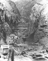
The river was diverted around the Dam site through four 50-foot diameter tunnels, two on each side of the river drilled through the canyon walls. The tunnel, with a total length of 15,946 feet, or about three miles, were excavated to 56 feet and lined with three feet (300,000 cubic yards) of concrete. The tunnels could carry over 200,000 cubic feet - more than 1.5 million gallons - of water per second! The river was diverted through the two Arizona tunnels on November 14, 1932.
After being used for river diversion, how were the tunnels used?
The inner tunnels were plugged with concrete approximately one-third their length below the inlets, and the outer tunnels were plugged approximately halfway. The two inner tunnels contain 30-foot diameter steel pipes which connect the intake towers in the reservoir with penstocks to the powerplant and canyon wall outlet works. The downstream halves of the two outer tunnels are used for spillway outlets.
What gates are installed on the tunnels?
The inlets of the two outer tunnels are permanently closed with 50- by 50-foot bulkhead gates. Each gate, with steel frame, weighs about 3,000,000 pounds, and required 42 railroad cars for shipment. At the outlets of the two inner tunnels, 50- by 35-foot Stoney gates are installed. These gates can be closed when the tunnels need to be emptied for inspections or repairs.
What are the intake towers?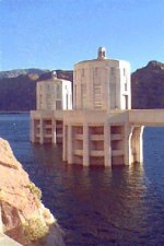
They are four reinforced-concrete structures located above the dam, two on each side of the canyon. The diameter of these towers is 82 feet at the base, 63 feet 3 inches at the top, and 29 feet 8 inches inside. Each tower is 395 feet high and each controls one-fourth the supply of water for the powerplant turbines. The four towers contain 93,674 cubic yards of concrete and 15,299,604 pounds of steel.
How are these towers connected to the powerplant and outlet valves?
By 30-foot-diameter penstocks (pipes) installed in 37- and 50-foot diameter concrete-lined tunnels. The upstream intake towers are connected to the inner diversion tunnels by 37-foot-diameter inclined tunnels; 37-foot-diameter tunnels also connect the downstream towers to penstocks and outlet works.
How do the intake towers control water flow?
Through two cylindrical gates, each 32 feet in diameter and 11 feet high. One gate is near the bottom and the other near the middle of each tower. The gates are protected by trash racks. Total weight of the gates is 5,892,000 pounds; the trash racks weigh 7,024,000 pounds.
What pipes are installed in the tunnels for reservoir outlets?
There are 4,700 feet of 30-foot-diameter pipe and 2,000 feet of 8 1/2-foot-diameter pipe. Maximum thickness of the largest pipe is 2 3/4 inches.
How are the 30-foot-diameter pipes connected to the powerplant turbines?
By sixteen 13-foot-diameter plate steel penstocks installed in 18-foot-diameter concrete-lined tunnels. Total length of these penstocks is 5,800.
What are the main characteristics of the penstock and outlet pipes?
Forty-four thousand tons of steel were formed and welded into 14,800 feet of pipe varying from 8 1/2 to 30 feet in diameter. Each length of the largest pipe - 12 feet long, 30 feet in diameter, and 2 3/4 inches thick - was made from 3 steel plates, of such weight that only two plates could be shipped from the steel mill to the fabricating plant on one railroad car. Two such lengths of pipe welded together make one section weighing approximately 135 tons or, at intersections with the penstocks, as much as 186 tons.
What outlets are used?
Four 68-inch jet flow gates inner diversion tunnel plug outlet; and two 90-inch jet flow gates each in the Arizona and Nevada canyon wall outlet works (also know as the valve houses). The jet flow gates in the canyon walls are about 180 feet above the river. The gates are designed to bypass water around the dam under emergency or flood conditions, or to empty the penstocks for maintenance work.
What are the Arizona and Nevada spillways?
Concrete-lined open channels about 650 feet long, 150 feet wide, and 170 feet deep on each canyon wall. More than 600,000 cubic yards of rock were excavated for spillways. The spillway walls are lined with 18 inches of concrete and the floors with 24 inches; 127,000 cubic yards of concrete were placed for the spillways.
How is water discharged from the spillways?
Into the outer diversion tunnels through inclined shafts 50 feet in diameter and 600 feet long. The discharge is controlled by four automatically or manually operated 100- by 16-foot, 500,000-pound drum gates on each spillway crest. Maximum water velocity in the spillway tunnels is about 175 feet per second, or 120 miles per hour.
What is the maximum discharge capacity of the spillways, jet flow gates and powerplant?
About 500,000 cubic feet per second (cfs). Each spillway can discharge 200,000 cfs. If the spillways were operated at full capacity, the energy of the falling water would be about 25,000,000 horsepower. The flow over each spillway would be about the same as the flow over Niagara Falls, and the drop from the top of the raised spillway gates to the river level would be approximately three times as great.
Source - U.S. Department of the Interior - Bureau of Reclamation